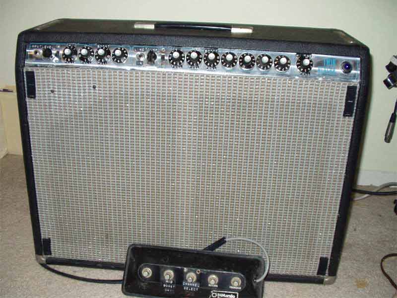
The front view shows the panel modifications and the 5 switch foot pedal. The front panel has only one guitar input with a signal attenuation switch immediatly to the right. Close to the middle of the panel are line in/out jacks. A compression control is next to the in/out jacks. Most of the original Fender control pots have been replaced with push/pull switch control pots similar to the original Master Volume pot. Notice that the Fender Logo has been removed from the grill - because inside it's no longer a Fender design. The black velcro strips support a 1/4 inch piece of plywood cut to the size of the grill for protection during transportation.
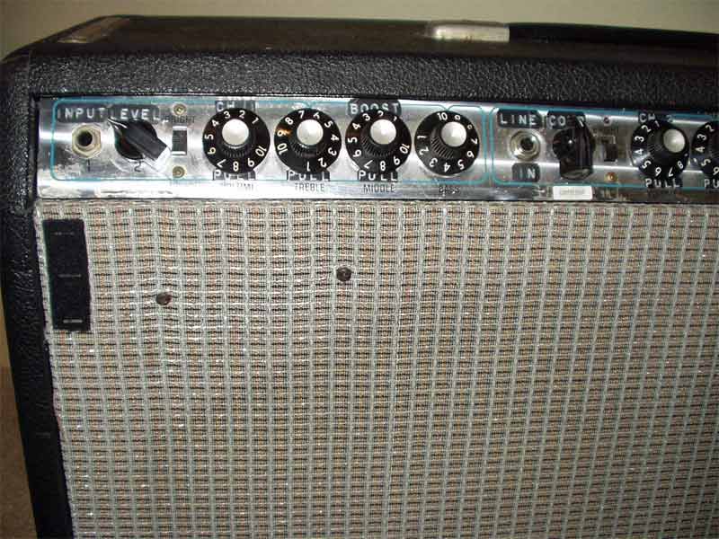
This closeup of the left panel side shows the single input jack and the 4 position rotory level switch. Also shown is the Line-in jack the compression control switch and the compression LED just above the bright switch. Most of the regular control pots have been changed to push/pull switches with various functions.
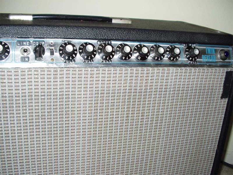
This view of the right panel shows the Master volume push/pull switch which has a new purpose. With the switch 'in', two of the 4 6L6 output tubes are switched out of the circuit; 'out', is full power.The Master volume pot has been moved to the output of the 2nd channel preamp (the old tremelo channel) for overdrive control.
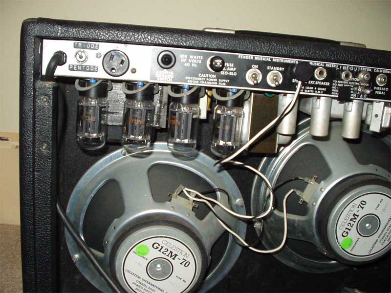
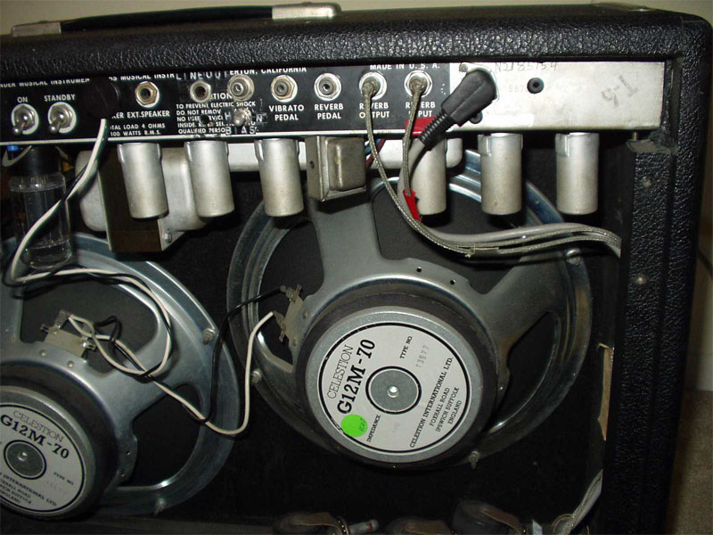
Rear view showing the 2 - 16 ohm celestion speakers in parallel for 8 ohms.
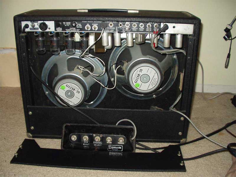
Closeup of the rear left rear panel shows the output tube 'triode' to 'pentode' mode switch (I prefer the tone of the triode mode). Also shown in front of each 6L6 tube are blue test jacks for output tube current measurements.
This closeup of the right rear panel shows the input for the 5 button foot pedal used to control channel switching, reverb, tremelo, and middle gain of the 2nd channel. A 5 pin DIN connector was used. Notice that the original vibrato and reverb inputs are no longer used. Also a 3 way bias switch to control output tube current can (barely) be seen.
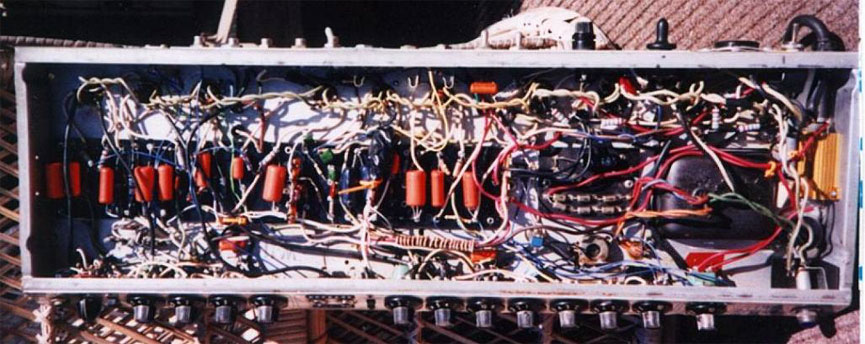
This amplifier has been completly rewired because the original circuit board had become conductive causing random noise and strange behavior. All resistors and capacitors have been replace. Notice the gold colored power resistors mounted at the far right. These are surge resistors for lowering the B+ voltage.
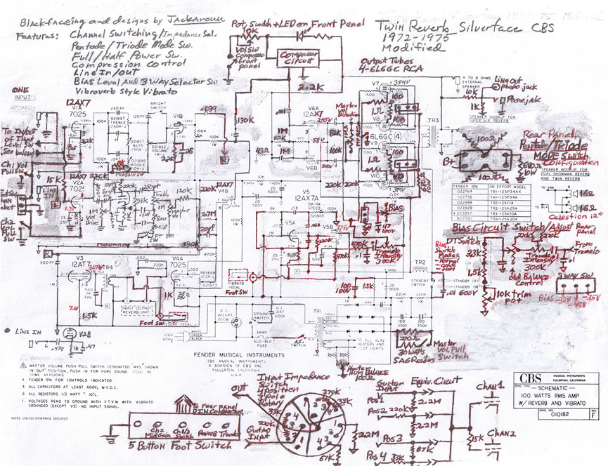
- Modified to "Black Face" specifications (AB763)
- Sag Resistors - reduce B+ from 435Vdc to 365Vdc
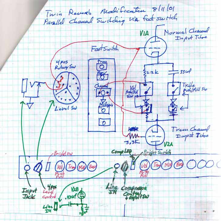
- Redesigned fender inputs to only one input jack with the signal common to both 12AX7 channel tube grids. Switching is via foot switch that lifts either of the pre-amp tube cathodes from ground
- Five button foot switch connected to rear of the chassis via a DIN plug. The foot switch has reverb, tremolo chan switching, mid boost
- Redesigned all foot switching to use low impedance cathodes to prevent transients; this keeps switching quiet without using reed relays or the need for individual shielded cables
- Reverb & Tremolo was added to both amplifier preamp channels
- Triode / Pentode Mode Switch (Triode mode uses 100 ohm screen grid resistors)
- Hi / Low power switch via Master Vol Pull switch (lifts cathodes of 2 of the 4 6L6 OTs)
- Master Vol Potentiometer is now placed after the channel 2 output tube for peamp overdrive control
- High level Line-In on the front panel - formally the channel 2 input jack
- Four position Input impedance selector on the front panel next to the single guitar input.
- Vibrato circuit was re-configured to output tube bias modulation (ala Vibroverb). This eliminated the pulsed neon bulb; the vibrato (tremelo) oscillation frequency was slowed down
- Compression circuit: compression level pot with on/off switch was added using the old #2 input jack on channel 2. An LED indicator was also placed on the front panel using one of the bright switches screw holes. The compression circuit itself is simple LED and photo resistor combination with added frequency filtering.
- Output Tube Bias (grid bias current) can be controlled with a 3 way switch placed on the rear panel (cool/warm/hot ~30/40/45 milliamps respectfully)
- The balanced bias potentiometer was changed to a bias level control with trim pot
- Test pin jacks (4) were placed on the rear chassis to measure each output tubes bias across a 1 ohm cathode resistor also placed between cathode and ground of each 6L6 output tube
- Fender JBL speakers were replaced by 2 Celestion 12" G12M-70 watt 16 ohms in parallel = 8 ohms
- Original RCA 6L6GC output tubes from 1972 (still in operation)
- Heater balance control pot placed accross the power supply transformer windings for tube filament AC hum control
- Feedback circuit in the power section was modified to 2.2k / 47 (ohm) ratio from 800/100 ohm ratio
- New circuit board added, new filter choke, new electrolytic capacitors, all new coupling and bypass capacitors, and new resistors.